BMS Main 2.1 (End of Life)
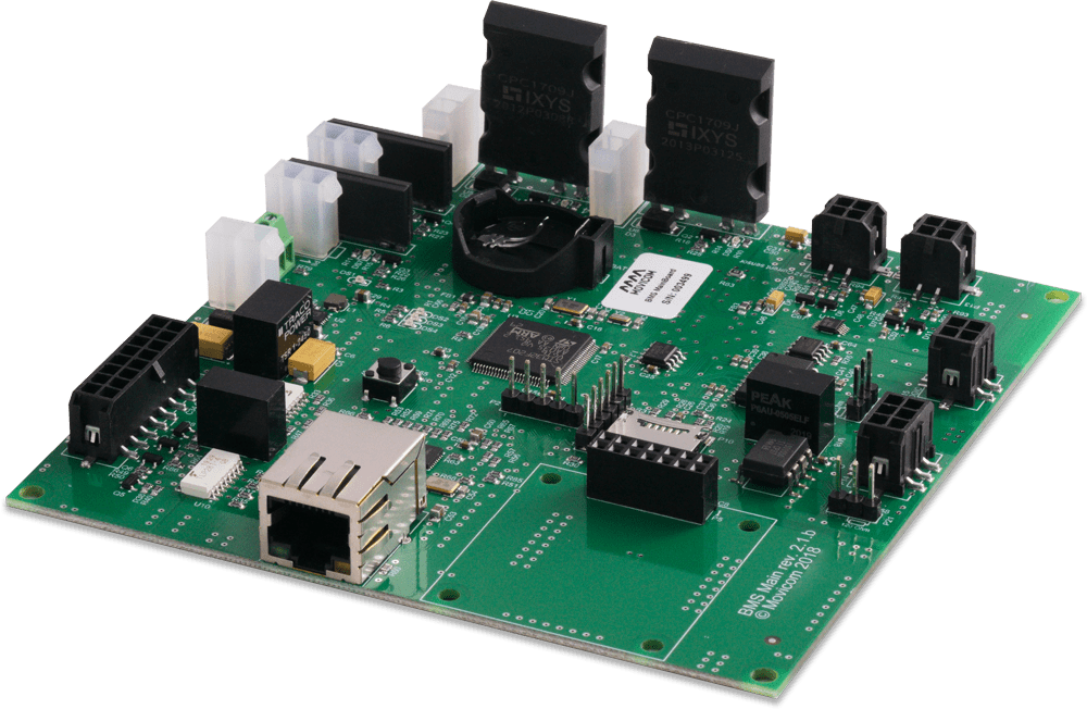
Controller
Modular BMS for 24-1200V batteries
BMS Main 2.1 interacts with measuring modules, calculates the battery state, and protects the battery from damage.
BMS Main 2.1 can control up to 23 measuring modules and manage a battery consisting of 414 cells.

- 4 solid-state relays for contactors
- 4 discrete inputs
- 4 discrete outputs

- SOC, DOD, SOH estimation
- Cycles, energy counting

- CAN, RS-485, Ethernet
- Wi-Fi (over an extension module)

- SD-card logging
- IoT ready
 Documentation
 ElectricDeviceMonitor
Compatible controllers: BMS Main X
Compatible measuring modules: BMS Logic 12S, BMS Logic 12, BMS Logic 18, BMS Logic 2.0
Compatible displays: BMS Display, BMS Indication
| Parameter | Value |
|---|---|
| Supply voltage, V | 9 to 30 |
| Current consumption @12 V, mA (max) | 100 |
| Number of BMS Logic devices | 1 to 23 |
| Number of cells (maximum) | 414 |
| Number of programmable solid-state relays for contactors (55V, 3A) | 4 |
| Number of programmable discrete inputs (dry contact) | 4 |
| Number of programmable discrete outputs (+5V, total 200mA) | 4 |
| Current sensor type | Hall-Effect sensor, bidirectional, supply voltage 5 V (LEM series HASS, HTFS) |
| Current sensor signal measurement error, V (maximum) | ± 0.001 |
| Number of CAN interfaces | 1 |
| CAN bus speed, kbps | 125, 250 (default), 500, 1000 |
| Number of RS-485 interfaces | 2 |
| RS-485 baud rate, bps | 600, 1200, 2400, 4800, 9600 (default), 19200, 38400, 57600, 115200 |
| CAN output voltage, V | 5.0 ± 0.5 |
| CAN output current, mA (maximum) | 400 |
| Number of Ethernet interfaces | 1 |
| Ethernet speed, Mbps | 10/100 |
| Dimensions (length × width × height), mm | 120 × 120 × 17 |
| Weight, g | 100 ± 10 |
| Operating temperature range, °С | -40 to +85 |
| The degree of protection from external influences | IP00 |
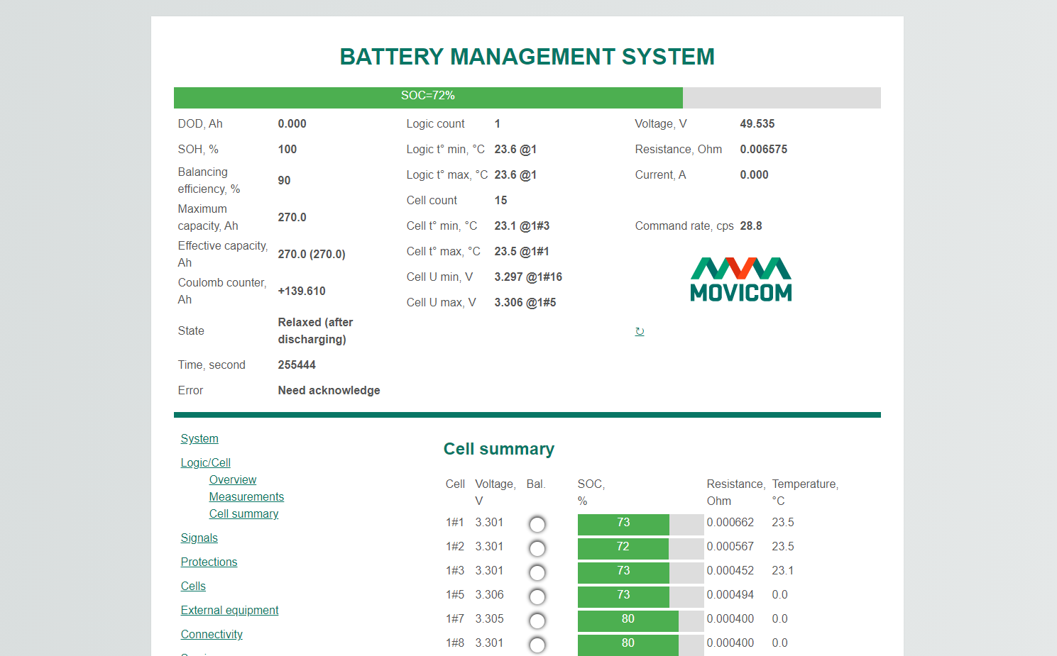
BMS Main 2.1 can be configured using the web interface over Ethernet or a Wi-Fi network (in this case, the BMS Wi-Fi module must be installed).
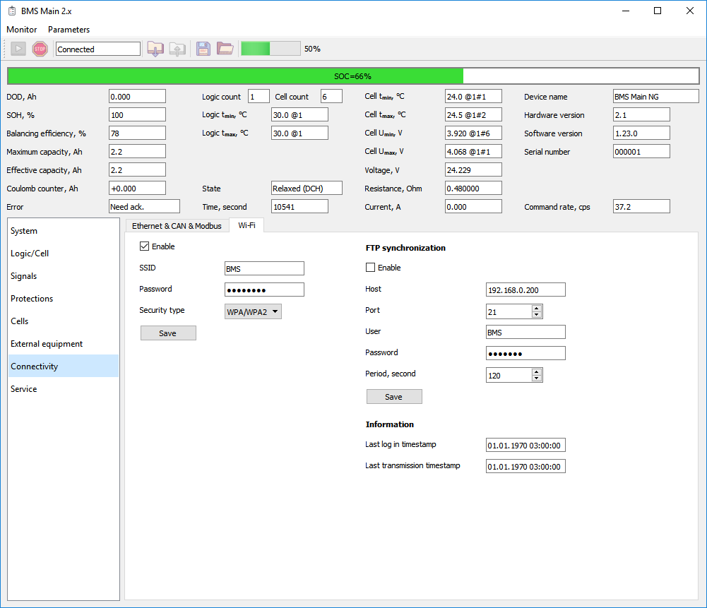
Another way to configure BMS Main 2.1 is to use ElectricDeviceMonitor software. A USB-CAN adapter is required to connect to the device.